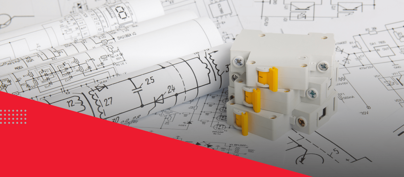
Electrical Computer-Aided Design (ECAD) software is used to create and modify both 2D and 3D diagrams and layouts bringing boundless benefit to the design, assessment, and documentation of electrical Printed Circuit Boards (PCB).
ECAD software can be used in the development process too.
Either as a diagram or abstractly. ECAD provides full detail as a layout or 3D assembly. Users can build out different options and alternatives, comparing them distinctly.
Released to manufacturing as part of the specification used to source, fabricate, and produce PCBs.
ECAD software provides some of the following capabilities and combinations.
Allow engineers to define the most appropriate electronic components and extremely accurate signals used to connect them. A company-standardized library that is centrally controlled allows Engineers to select the right components.
Offer means to create PCB’s outline and dimensionally place components within boundaries. These capabilities can be applied in either 2D or 3D models. The list of electronic components used in the diagram is carried over to the layout, where it practically becomes a to-do list for placement.
Let engineers to define the path that the trace follows in a specific layer of the PCB between the electronic components. This can be done in 2D or 3D, by switching between layers of the PCB.
The signals from the diagram, which embody from-to information between components, are carried over into the layout, which defines the placement of each component on the PCB.
Trace the routes between the different components based on interconnect information and can be customized.
Offer a means to create a 3D model of the PCB. These models are regularly used to check for interference in an enclosure as well as checking for manage the dissipation of heat from electronic components on the PCB.
Deliver tools to capture and manage feedback amongst individuals within a team developing a routed system.
Offer the ability to visualize the design of the routed system. This is significant for non-technical roles that do not have the skills or knowledge to use RSD software directly.
Allow persons to capture their feedback in the context of the design of the routed system.
Deliver the capabilities to diagram and layout multiple PCBs that work together as a single system. IC and PCB Co-Design capabilities provide a means to assimilate Integrated Circuits (IC) processors into the PCB, optimizing how traces connect to compact footprints.
Enable multiple team members to work in parallel on the same PCB or multi-board PCB design.
Instinctively compare the design of a PCB with industry benchmarks or company rules, highlighting the violations or issues that could affect performance or the manufacturability of the PCB.
Provide the capacity to generate ECAM deliverables, that can be used to manufacture layers of the PCB.
Proficiencies automatically generate the list of electrical components for the PCB.
ECAD software can produce several different deliverables, that can be managed by Product Data Management (PDM) software.
Designs from ECAD software are frequently exchanged with Mechanical Computer-Aided Design (MCAD) software to produce a 3D model of the PCB.
© 2026 Solidpro. Designed with passion @ Spidergems Softlabz